Change Log Kalypso 13.12
From KalypsoDev
Changes since: Kalypso-12.11.0 Detailed changes (Trac): http://dev.bjoernsen.de/kalypso/report/35
Please also pay attention to the compatibility notes (german only).
Contents |
Kalypso Platform
Items that improve Kalypso in general.
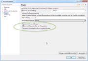
Two new user preferences allow to change the behavior of the mouse wheel in the map:
|
|
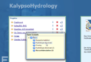
| When activating a project via the welcome page, a popup dialog will be shown that allows to select which scenario will be opened, if the project contains more than once scenario. | |
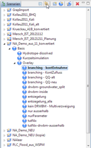
| A new action in the scenario view allows to jump to the currently active scenario. Useful for workspaces with many projects and scenarios. |
Consumability / Reliability
Items that make it easier for users to get Kalypso, install it on their systems, and configure it for their use.
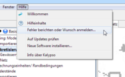
| A new entry in the help menu allows to directly post an error or enhancement to the Kalypso ticket system. | |
| The default memory setting (-Xmx in kalypso.ini, see manual) for the 64bit version of Kalypso has been set to 3 GB, which should be a good default value for most 64bit systems. |
KalypsoHydrology
| KalypsoHydrology now supports the new SUDS elements (overlay elements). SUDS (sustainable urban drainage systems) are used as measures in urban areas to de-centrally extend the available retention volume. Hydrology implements these SUDS in a very generic way using additional drainage abilities in soil horizons, allowing to define your own SUDS. Standard parameters for common SUDS such as green roofs, swales, swales and trenches are pre-defined in the project template. | |
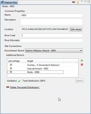
Two new relations between net elements have been introduced:
|
|
| All (including new) kind of relations between net elements now also show up in the table overviews of the net. This allows the user to have a quick overview of which elements relate to each other. | |
| The result management now scales better for scenarios containing a big number of simulations with many results and opens the view much faster. The results of each simulation are now loaded on demand when the use opens the simulation in the result view. | |
| The result management low allows to delete all results of a scenario at once in order to clean up a project. Optionally, the 'most recent' result can be excluded from deletion. | |
The simulation has been improved in many small ways including:
|
|
| When copying or deriving a scenario from another, it is now possible to copy the scenario without existing result data, making this operation very fast for big datasets. | |
| The result timeseries are now saved in a compressen format, reducing the required disc space of a simulation result by about 80%. | |
| Hydrology now supports a new timeseries format called 'DWD daily values', see [1]. | |
| The timseries format DWD-md has been reworked in order to handle missing values. | |
| The validation of storage channel parameters has been improved in order to check for violation of minimum/maximum volume limits. | |
| The handling of selected output elements has been improved in such a way that it is now possible to select a single sub-catchment or a single channel for simulation. Hydrology will then simulate only the sub-net containing this single element. | |
| It is now possible to re-import net elements (nodes, channels, sub-catchments) from a shape file into existing projects. This especially allows to add or update existing net elements. |
KalypsoWSPM
The SOBEK ASCII Export has been improved in several ways:
|
|
| A new tool of the cross section view allows to exchange points between the main section and section sub-parts. For examples points of an additional sub-part can now be declared as to be points of the upper edge of a bridge. | |
| Coded Tripple Import: There is now an import for tripple profiles with a additional name and code. The name contains the station of the profile (e.g. '03.462_67'). The import can be configured with property files, to assign point codes to the profile or horizons (generic horizons or Kalypso horizons). | |
EWAWI Import: In the EWAWI import wizard there is now an option for enabling/disabling projection of the profile points on a idealized line.
|
|
| The profile table now shows a tooltip for problem icons. | |
| The profile chart now shows problems in the cross section as small warning/error icons. Touching the icon with the mouse will show the corresponding warning message as tooltip. | |
| In order to correctly define bridges and weirs with multiple disconnected segments, it is now possible (and necessary) to mark the start and end points of each segment of the the bridge resp. weir. The start and end markers are entered in a new data column of the cross section table. | |
| When exporting cross sections to the WspWin format .prf using the option 'Knauf', or when exporting to the .wspr Format, cross sections containing buildings (bridges, weirs, culverts) are now automatically split up into several cross section parts ('Mehrfeldbrücken'). An additional, optional, theme in the outline of the cross section chart gives a preview of how this split would take place. This layer can be activated or deactivated in the user preferences of WSPM. | |
| When importing cross section from a WspWin LWA project (Knauf project), WSPM now detects cross sections that are devided in multiple parts ('Mehrfeldbrücken'). Such sections are now automatically combined into one single cross section in Kalypso. |
Kalypso1D2D
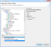
Kalypso now allows to access result data from outside the current scenario (i.e. the scenario that is currently edited). The following is now possible:
|
|
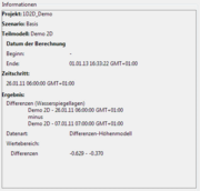
| The description of difference results (i.e. results generated by subtracting two result tins), now contains information about it's sources and the data type.. | |
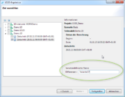
| It is now possible to set a user defined name to a difference of result tins. | |
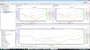
| It is now possible to open multiple longitudinal section at once. It is additionally possible to open longitudinal sections originating from scenarios other than the currently active one. | |
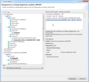
| The dialog for selecting restart results for a simulation has been reworked. In addition to a simpler user interface, it is now possible to select restart results from arbitrary projects and/or scenarios. | |
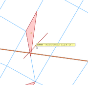
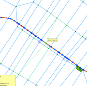
| A new quality check for the finite element mesh has been introduced. The mesh is validated in the background and a new map layer shows the validation problems in the map. The info tooltip of this problem theme showsn the validation problem message. | |
Several usability improvements concerning the channel editor:
Additionally, several bugs have been fixed as well. |
|
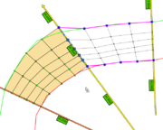
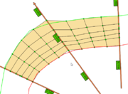
| The channel editor now checks if a cross section lies on the boundary of the existing net. If this is the case, the channel editor will derive the cross section from the boundary of the net in order to create a smooth transition between the existing net and the newly created channel. | |
| When editing 2d-elements by moving a node, it is now possible to snap to any other vector theme. The user also has the choice to assign the z value of the snapped geometry to the moved node. More or less any vector theme can be used to snap nodes, such as imported shape files, cross sections, etc. | |
| A new export method allows to write the border of the net into a PolygonZ shape file. Node elevations are used as z-values and holes in the net are correctly handled. | |
| In the 'Assign Elevations' widget there is now a 'Remove Elevations' button for resetting the elevations of all selected nodes. | |
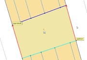
| When editing the properties of a 2D-control structure (2D weir), a preview of the orientation of the structure is now shown to the user. | |
| The validation and log output when running the simulation has been improved. More log messages are now georeferenced, so clicking on most log messages in the simulation log will show the right location in the map. | |
| It is now possible to define the maximum water level for 2D-control-structures. If the water level exceeds the given maximum during simulation, the structure is automatically deactivated by RMA-Kalypso. |
KalypsoFlood
| EXPERIMENTAL: it is now basically possible to use a triangulated surface (instead of a grid) as digital height model.
The triangulated surface can be imported via the menu 'Manage Digital Terrain Data'. Supported formats are HMO, ESRI Shape PolygonZ-Triangles and SMS 2dm Format. During flood processing, the trinagulated surface will be automatically converted into a grid, currently with a fixed cell size of 5 meters. |
KalypsoRisk
It is now possible to define damage functions using the 'min' operator, which allows to choose the minimum between two damage values. For example the following formula is possible: 10 min (10*x)which uses the damage function 10*x up to a maximum of 10. |
