Difference between revisions of "NetLinkages/OverlayLinks/hydrology/en"
From Kalypso
| Line 19: | Line 19: | ||
[[Category:Hydrology]] | [[Category:Hydrology]] | ||
| − | {{Languages| | + | {{Languages|Contents/hydrology}} |
Latest revision as of 14:13, 15 November 2021
[edit] Creation of overlay linkages
[edit] change of perspective
Linking the overlays is a function in the perspective "Kalypso Modeller". The change of perspective is explained here: Change perspective. The standard perspective is the "Kalypso Workflow", which is changed here to "Kalypso Modeller". This view displays the tree structure of the models and displays additional functions.
[edit] Creation of overlay linkages
The aim of linking the overlays is to simulate a controlled flow of an overlay element (SUDS, e.g. green roof, swale, cistern) to a target element. A target element can be another overlay element within the subcatchment or a node in the bottom of the network tree.
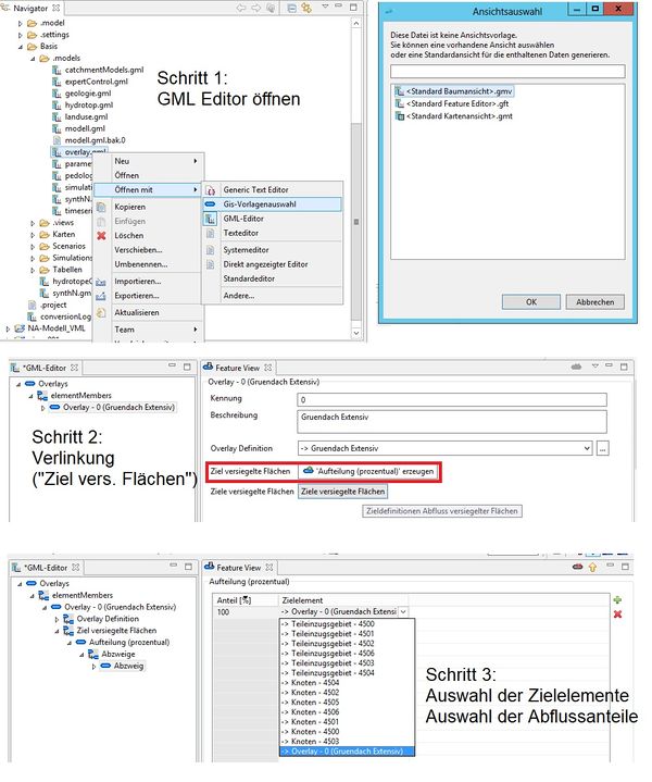
The steps to create linkages among overlays are illustrated in the figure Steps to link Overlay elements via the Modeller Perspective. and are explained below:
- Step 1 Open the Overlay Features
- The features of an overlay in a model are opened in the tree structure using the following path: ‘NA-Modell Name’ —> Base —> (if applicable, scenarios —> ‘Name Scenario’) —> .models —> overlay.gml. The "Tree Structure" allows you to open the item's Feature View.
- Step 2 Linkages
- The overlay element is linked by specifying a target for a "sealed" surface area. In this case, this function is taken from the sub-catchment functions and means that the horizontal outflow of the area (here: overlay element) can be drained to a target (as portion or complete: 100%). By default, the flow from an Overlay element is drained to the node of the subcatchment where the Overlay element is located in. By such a linkage, the outflow is "redirected" to a defined target within the subcatchment (other overlay elements) or in the lower reaches of the hydrological network (other overlay elements or nodes).
- Step 3 Definition of target element and percentage of discharge.
- With the green "plus" button a new target can be defined. The target can be selected from a menu of all the available network elements (nodes, subcatchments and overlays) in the model. Several targets can be selected and percentages up to a maximum of 100% can be specified.
| Language: | English • Deutsch |
|---|
