Difference between revisions of "NetLinkages/hydrology/en"
BhawaniRegmi (Talk | contribs) (Created page with "= Create Net Linkages = == Ansichten zur Bearbeitung der Netzverknüpfung == Ansichten der Netzverknüpfung Der Systemvernetzung kan...") |
BhawaniRegmi (Talk | contribs) |
||
| Line 1: | Line 1: | ||
= Create Net Linkages = | = Create Net Linkages = | ||
| − | == | + | == Views for processing Network Linkage == |
| − | [[File:Netzverknuepfung.jpg|thumb|400px| | + | [[File:Netzverknuepfung.jpg|thumb|400px|Views for processing Network Linkage]] |
| − | + | The system network can be defined in two different ways, either in the map with ''Network links'' or in the tables of the Feature View of the ''Network element'' view. | |
| − | + | The elements depicted in the map can be processed with the tools in the ''Network Linkage view''. In the ''Network Linkage View'' the geometries are displayed as point members. | |
| − | + | ||
{{Clear}} | {{Clear}} | ||
| − | == | + | ==Procedure for the network linkage == |
| − | + | The linkage of the network of the model is based on the geometries of shape files. | |
| + | The relations can be edited in the map with the ''Map Features'' tool view. This view is applied to set relations and it reduces the scope of possible relations to make a clear network structure. | ||
| − | + | # First, the individual relations can be selected using the respective check box: weather switched on or off. | |
| + | # Secondly, to connect the linkage use ''Pull'' though a connection with the mouse. To do this, the top element is selected by clicking the left mouse button, select ''Hold''. If one pulls the connection on the main element, a green dotted line is visible. Once, the desired linkage is displayed in this manner, the mouse button can be released to set the connection. The relationship is symbolized by an arrow of the corresponding colour of the output element. (According to the representation of the chosen styles) | ||
| + | |||
| + | The course of the water system is defined by relations of strands to nodes and further on from nodes into strands. The linkages are placed respectively in the flow direction. | ||
| − | + | In the resulting water system, the sub catchments are connected by a relation to a strand in the overall network plan(drainage of the sub catchments is carried out on the downstream nodes of the strand). | |
| − | + | In addition, the linkage of the underground catchment area, the groundwater system is represented by the linkage of the sub catchment options: ''Sub catchments'' -> (Groundwater) -> For this relations edit the map view, select tools sub catchment in the menu -> ''Sub Catchments'' and proceed as described in connection above a branch with the left mouse button and selected. | |
| − | + | {{Info_tip|The sub-catchment areas are connected by linking the network of the relation between the sub-catchments to the strand. But calculating the simulation is part of drainage at the downstream node of the strands.}} | |
| − | + | === Node to Node Relationships === | |
| + | [[File:Hydrologie_Modelaufbau_Netzverknüpfungen_Verzweigungen.PNG|thumb|250px|Node to node option wizard]] | ||
| + | The model node can be considered as link elements for the model. In addition to the General information and time-series links, node parameters include therefore the node-to-node ratios, which allow to model a waters branch. | ||
| − | + | To do this, a corresponding relation (node to-node relationship) can be made first in model networking in the map view. After this step, automatically a wizard opens , where the desired connection type can be selected from four relationships (overflow, withdrawal, QQ relations, branch, inflow or over flows (see Figure [[:File:Hydrologie_Modelaufbau_Netzverknüpfungen_Verzweigungen.PNG|''Node selection wizard'']]). Then, the information of the flow distribution type of the node can be seen in the table of the network elements in the feature view. Or the node to node relationship is made directly in the feature view. | |
| − | + | The node-to-node relationship includes: | |
| + | ; Distribution (in percent) | ||
| + | : The distribution branch can be derived proportionally from the outflow to another node. The input here includes the shared part in [%] as a number (double) and the selection of a destination node. This function corresponds to the function for '''branching'''. | ||
| − | + | ; Discharge | |
| − | + | : When a discharge rate of the nodes are removed and discharged to another node in the system or an external node. The removal amount is specified in [m³ / s]. The destination node may be selected from the drop-down menu. | |
| − | + | ||
| − | + | ||
| − | + | ||
| − | + | ||
| − | + | ||
| − | + | ||
| − | + | ||
| − | + | ||
| − | + | ||
| − | ; | + | |
| − | : | + | |
{{Clear}} | {{Clear}} | ||
[[File:Hydrology_Zeitreiheneditor_QQAbschlag.png|thumb|250px|right|Zeitreiheneditor zur Bearbeitung einer QzuQ Beziehung.]] | [[File:Hydrology_Zeitreiheneditor_QQAbschlag.png|thumb|250px|right|Zeitreiheneditor zur Bearbeitung einer QzuQ Beziehung.]] | ||
| − | |||
| − | |||
| − | ; | + | ; Q-Q distribution |
| − | : | + | :With this type of branch a relative percentage of the current flow in the node is drained to a different node. The editing of the Q-Q relationship is done with the time series editor and is shown in the figure[[:File:Hydrology_Zeitreiheneditor_QQAbschlag.png|QQ- relationship]]. For details on the handling of the time series editor,(see Figure [[Parameterdefinition/Zeitreiheneditor/hydrology/de|Zeitreiheneditor]]). This branch type replaces the function of the '''Additional withdrawal'''. The selection of the destination node is done via the drop-down menu. |
| + | |||
| + | ; Branch | ||
| + | : Using the branch relation enables the drainage of a portion of runoff between 0 and 1 to a target node. It is the proportion of the entered branch (double) and selected target node from the drop-down menu. | ||
| − | ; | + | ; Inflow |
| − | : | + | : A constant inflow [m³/s] can be defined to the flow of the node. |
| − | ; | + | ; Overflow |
| − | : | + | : In this branch an overflow amount of run off is defined in [m³ / s]. At excess of this outflow the resulting effluent is discharged to a destination node. The height of the overflow is a numerical number (double) and the destination node can be selected from the drop-down menu. |
| − | {{Info_tip| | + | {{Info_tip| After selecting the relation node → (e.g. node to node) → the branch as the connection type can be selected (between 0 and 1) in the Feature View and the branching portion can be inserted later in the table view.}} |
[[Category:Hydrology/en]] | [[Category:Hydrology/en]] | ||
{{Languages|Create Net Linkage/hydrology}} | {{Languages|Create Net Linkage/hydrology}} | ||
Revision as of 18:48, 15 February 2017
Contents |
Create Net Linkages
Views for processing Network Linkage
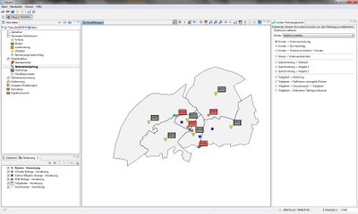
The system network can be defined in two different ways, either in the map with Network links or in the tables of the Feature View of the Network element view. The elements depicted in the map can be processed with the tools in the Network Linkage view. In the Network Linkage View the geometries are displayed as point members.
Procedure for the network linkage
The linkage of the network of the model is based on the geometries of shape files. The relations can be edited in the map with the Map Features tool view. This view is applied to set relations and it reduces the scope of possible relations to make a clear network structure.
- First, the individual relations can be selected using the respective check box: weather switched on or off.
- Secondly, to connect the linkage use Pull though a connection with the mouse. To do this, the top element is selected by clicking the left mouse button, select Hold. If one pulls the connection on the main element, a green dotted line is visible. Once, the desired linkage is displayed in this manner, the mouse button can be released to set the connection. The relationship is symbolized by an arrow of the corresponding colour of the output element. (According to the representation of the chosen styles)
The course of the water system is defined by relations of strands to nodes and further on from nodes into strands. The linkages are placed respectively in the flow direction.
In the resulting water system, the sub catchments are connected by a relation to a strand in the overall network plan(drainage of the sub catchments is carried out on the downstream nodes of the strand). In addition, the linkage of the underground catchment area, the groundwater system is represented by the linkage of the sub catchment options: Sub catchments -> (Groundwater) -> For this relations edit the map view, select tools sub catchment in the menu -> Sub Catchments and proceed as described in connection above a branch with the left mouse button and selected.
| The sub-catchment areas are connected by linking the network of the relation between the sub-catchments to the strand. But calculating the simulation is part of drainage at the downstream node of the strands. |
Node to Node Relationships
The model node can be considered as link elements for the model. In addition to the General information and time-series links, node parameters include therefore the node-to-node ratios, which allow to model a waters branch.
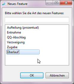
To do this, a corresponding relation (node to-node relationship) can be made first in model networking in the map view. After this step, automatically a wizard opens , where the desired connection type can be selected from four relationships (overflow, withdrawal, QQ relations, branch, inflow or over flows (see Figure Node selection wizard). Then, the information of the flow distribution type of the node can be seen in the table of the network elements in the feature view. Or the node to node relationship is made directly in the feature view.
The node-to-node relationship includes:
- Distribution (in percent)
- The distribution branch can be derived proportionally from the outflow to another node. The input here includes the shared part in [%] as a number (double) and the selection of a destination node. This function corresponds to the function for branching.
- Discharge
- When a discharge rate of the nodes are removed and discharged to another node in the system or an external node. The removal amount is specified in [m³ / s]. The destination node may be selected from the drop-down menu.
- Q-Q distribution
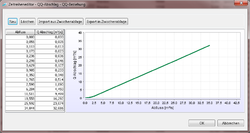
- With this type of branch a relative percentage of the current flow in the node is drained to a different node. The editing of the Q-Q relationship is done with the time series editor and is shown in the figureQQ- relationship. For details on the handling of the time series editor,(see Figure Zeitreiheneditor). This branch type replaces the function of the Additional withdrawal. The selection of the destination node is done via the drop-down menu.
- Branch
- Using the branch relation enables the drainage of a portion of runoff between 0 and 1 to a target node. It is the proportion of the entered branch (double) and selected target node from the drop-down menu.
- Inflow
- A constant inflow [m³/s] can be defined to the flow of the node.
- Overflow
- In this branch an overflow amount of run off is defined in [m³ / s]. At excess of this outflow the resulting effluent is discharged to a destination node. The height of the overflow is a numerical number (double) and the destination node can be selected from the drop-down menu.
| After selecting the relation node → (e.g. node to node) → the branch as the connection type can be selected (between 0 and 1) in the Feature View and the branching portion can be inserted later in the table view. |
| Language: | English |
|---|


