Difference between revisions of "Hydrotop/hydrology/en"
BhawaniRegmi (Talk | contribs) (→Hydrotope (Tabele)) |
BhawaniRegmi (Talk | contribs) (→Hydrotope (Tabele)) |
||
| Line 32: | Line 32: | ||
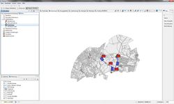
[[File:Hydrotope Karte.jpg|thumb|250px|right| View of Hydrotope (Map)]] | [[File:Hydrotope Karte.jpg|thumb|250px|right| View of Hydrotope (Map)]] | ||
{{Clear}} | {{Clear}} | ||
| − | === Hydrotope ( | + | === Hydrotope (Table) === |
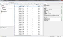
| − | [[File:Hydrotope Tabelle.jpg|thumb|250px|right| View of Hydrotope ( | + | [[File:Hydrotope Tabelle.jpg|thumb|250px|right| View of Hydrotope (Table)]] |
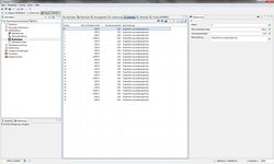
| − | creating the hydrotope, the data from the hydrotope are added to the table hydrotope (see Figure:[[:File:Hydrotope Tabelle.jpg| View Hydrotope ( | + | creating the hydrotope, the data from the hydrotope are added to the table hydrotope (see Figure:[[:File:Hydrotope Tabelle.jpg| View Hydrotope (Table)]]). The attributes of the hydrotope are summarized in the following table: |
Latest revision as of 19:45, 15 February 2017
Contents |
[edit] Hydrotope and Overlays
The data of Hydrotope can be imported as shape file when Creating a new project. However, it is recommended that the preparation and production of Hydrotope is done in the user interface of KalypsoHydrology. This is useful because the Hydrotope data changes over time (i.e. new land use development) and these changes may be done as a simple update. In addition to general information about the detailed Hydrotope characteristics and key reference data in the Hydrotope data is mainly intended for parameter catalogue.
[edit] Views for processing the Hydrotope data
To edit the Hydrotope the following views and tables are available:
- Hydrotope (Table)
- A list of all Hydrotope
- Hydrotope (Map)
- Map of the network elements and the Hydrotops of the model area.
- Sub catchments
- List of sub catchments, and the parameters for Hydrotope intersection.
- Land Use
- List of land uses and the parameters for Hydrotope intersection.
- Geology
- List of available geology data and the parameters for Hydrotope intersection.
- Pedology
- List of available Pedology data and the parameters for Hydrotope intersection.
- Overlay (DRWBM)
- List of available overlays and the parameters for Hydrotope intersection
[edit] Generate Hydrotope (Map View)
In the map view the network elements and the data are presented for the creation of hydrotope (see FigureView of Hydrotope (Map)). The data for the creation of hydrotope includes the data of land use, pedology, geology and (optionally) overlays. The parameter sets of data must be available before you import the shape data in the model. The creation of the parameter catalogue is described in the section: Parameter Definition.
Shape File Import: The import of the data is done via the map view of the hydrotope. “Import Wizard” is described here: Data Import for creating hydrotope.
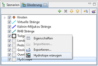
Generate Hydrotope : After importing the data, the hydrotope can be created. This is done via the function Generate hydrotopein the Outline view (see: Generate Hydrotope ).
[edit] Hydrotope (Table)
creating the hydrotope, the data from the hydrotope are added to the table hydrotope (see Figure: View Hydrotope (Table)). The attributes of the hydrotope are summarized in the following table:
| Hydrotope | |||||
| Name | Sub catchment | Land Use Area | Pedology | Geology | Overlay Area |
| [Text] | Sub-Catchments Number | Name of Land Use | Name of Pedology | Name of Geology | Name of Overlay |
Direct input of values of hydrotope
A direct input of the hydrotope values is no longer necessary in the current model. Only for editing the old projects, the direct input is still supported, if the references are not set on the input data. The direct input data are the following:
| Values | ||||
| Land Use Key | Soil Profile | Max. Percolationsrate [m/s] | Inflow portion to the ground water | Sealing rate factor |
| Existing use as the Key name, Which links to the use of the use parameters Represents the data usage collection |
Soil profile as the key name | Maximum Percolation
Rate into the ground water |
Portion of the ground water [Number(double)]** | Correction factor of the standard sealing grades the associated land use [Number (double)] |
'** As default, the Max. Percolation [m / s] is set to zero. In this statement there is no limitation of the Max. Percolation.
[edit] Sub catchments (Generate Hydrotope)
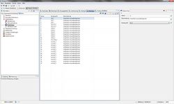
The table of the sub catchments summarizes the parameters that are involved in the hydraulic top intersection. The values are summarized in the following table and are listed in the view of the Sub catchments like in the figure View of the sub catchments.
| Sub catchment (Generate Hydrotope) | |||||
| Name | Description | TG-Area | Correction factor Sealing grades | Correction factor Percolations rate | Distribution factor of Ground Water |
| [Text] | [Text] | Number (long) | Number (double) [>0.00] | Number (double)[>0.00] | Number (double)[0-1] |
- Name
- Sub-catchment number consisting of 4 digits.
- Description
- Description of the sub-catchment area, such as the names of the associated water system.
- Sub-Catchment area
- The surface of the sub-catchment area is determined by the program when the shape file is imported. The calculation area comes from the Hydrotops associated to the sub-catchment area.
- Correction factors of the sealing rates
- Correction factor of the standard sealing level. The degree of sealing the associated land uses within a part area be corrected with this factor as a whole.
- Corrected Percolation rate
- Correction of the maximum rate of percolation (> 0.00). This percolation is used as a maximum. As default, the Max. Percolation [m / s] is set to zero. In this statement there is no limitation of the Max. Percolation.
- Distribution factor of Groundwater
- Correction factor to the distribution of groundwater in shallow and deep aquifers. This factor is between 0 and 1 indicating what percentage in the deep aquifer is discharged. By default, this is set to 1, which remains 100% in the flat upper aquifer.
[edit] Land Use (Generate Hydrotops)
The data of land use parameters to create the hydrotope is imported during the land-use data import in the table. The data forms the basis for the intersection and creation of the hydrotope.
| Land Use(Generate Hydrotope) | |||
| Name | Land Use | Corrected Sealing factor | Description |
| [Text] | Land use (Link) | Number(double) | [Import-Information from the Data] |
- Name
- This is used to assign elements of the shapefile to existing network elements
- Land Use
- Existing use key name, which is the link to the use of parameters of the land use data collection.
- Correction factor of sealing rate
- Is applied to the sealing class of land use type.
- Description
- Description of the Import-information data.
[edit] Geology (Generate Hydrotope)
Here, only the data is listed, which provides the important hydrotope data.
| Geology (Generate Hydrotope) | |||
| Name | Max. Percolation rate | Groundwater section | Description |
| [Text] | Number (double) | Number (double) | [Import-Information from the Data] |
It specifies the maximum percolation rate [mm/d] from the deepest (or lowest) layer of the soil in the groundwater section here.
| The proportion of ground water is specified as percentage [%]. The area given here remains in near-surface groundwater storage. This percentage is multiplied with the allocation the groundwater factor from the model parameters per area (see Sub catchments). If the derived value in the deep aquifers or near-surface aquifers is over 100%, a correction of the values is done. |
[edit] Pedology (Generate Hydrotope)
The data listed here, provides the important information for the hydrotope generation.
| Pedology (Generate Hydrotope) | ||
| Name | Soil profile | Description |
| Description | Soil profile (Link) | [Import-Information from the Data] |
The reference is made to the soil profile key during import. Prerequisite for the correct assignment is the full input of parameters for the soil before the import of the shape file.
[edit] Overlay (Hydrotope or part of Sub catchment generation)
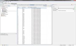
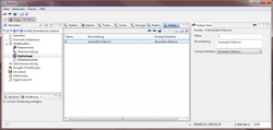
After the shape file of the overlays is imported, it can be transferred to the data in the table (see Figure: View of Overlay (DRWBM).
| Overlays (Generate Hydrotope) | ||
| Name | Description | Overlay Definition |
| [Text] | [Text] | Reference of Overlay Definition |
The name of the overlay is determined by the import. The description of the overlay can be taken from the attribute table of the shape file during import and can be edited. The networking/ linkage to the overlay definition is done during import. A precondition to import the correct file is, the previous entry of all input parameters(See: Parameter Definition of Overlays).
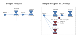
With the newly developed concept, new areal data objects (like quasi sub-sub-catchments) are created by the data units of the overlays. These subsidiary sub-catchments are obtained according to the information of the mother sub-catchments if no optional specified overlay records is specified by the modeler. The integration of new sub-catchments in the existing network is done via "on the fly" generated nodes. Schematically the integration of new sub-catchments is shown in the adjacent figure: Creation of sub-areas from overlays and integration into the network.
| If a groundwater extraction [m³ / s] is defined in the sub-catchment (see: Parameter sub-catchments), this groundwater extraction is applied even after the creation of new sub-catchments from the original sub-catchments. This ensures that a punctual or areal removal is maintained in the water balance of the entire catchment. |
| Language: | English • Deutsch |
|---|
