NetElements/hydrology/en
Contents |
Net Elements
The spatial discretization of catchments is carried out by dividing it into sub-catchments, strands and nodes (See: Digitization of network elements)
Views for editing the network elements
For the processing of network elements five views are available:
- Overview
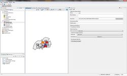
- Shows the model elements in the map overview (see Figure Overview of Network Elements. Items are selected in the following table views, so these are marked in the map with a yellow background colour and in the feature view the parameters of the selected element can be edited:
- Nodes
- Selecting the node to edit the parameters.
- Strands
- Selection of strands to edit the parameters.
- Sub Catchments
- Choice of catchment areas to edit the parameters.
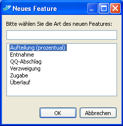
New network elements can be added in the map or in the table or can be removed. Alternatively the network elements can be actualized or updated by importing a shape file Network elements from a shape file.
Nodes
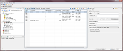
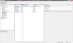
The other nodes serve as linking elements : Relationship Node to Node ). In addition to the general information and time-series links the node parameters include therefore, the network links to underwater strands and water branches. The view of the table is shown in Figure Node Table View
| Nodes | |||||
| Name | Description | Water Identification Code | Flow Kilometer | Downstream strand | Branch |
| [Text] | [Text] | Water Identification Code | Number [double] | Strands (Link) | For network links: Create a Branch |
- Name
- Node number consisting of 4 digits
- Description
- Description of the node (optional), E.g. gauging station name, name of the village.
- Water identification code
- Waters identification number (E.g. Country - Association of water) (optional)
- Flow Kilometre
- Water network (Optional)
Strands
The extrusion parameters initially divides the different strand types in parameters of the virtual strands, parameters of the real strands (Kalinin-Miljukov) and parameters of storage strands (flood retention basin strands). The parameters of virtual strands and real strands represent the basic data of an open water system, which are complemented with the storage strands or by special parameters.
| Basic data of the strands | |||
| Type | Name | Description | Down stream nodes |
| Strand type | [Text] | [Text] | Downstream nodes (Link) |
- Name
- Strand number consisting of 4 digits ( see: Network link).
- Description
- Description of the strand, E.g. name of the River, the name of the retention basin.
- Downstream (Link)
- Relation to the draining node of the strand.
Storage strands
Through the flood discharge system routine (two additional branches (1 output and 2 branches) can be simulated in addition to the usual flood retention basins (HRB) drained through only one bottom outlet (underwater node) and the exceeded flow outlet. It enables the simulation of a withdrawal quantity which depends on the water level (in the WVQ relationship = Water level-Volume-Discharge-Relationship) and can be discharged to a different node in the model network. In addition, Lake Evaporation dependent on the season can be defined(see Time series mapping in simulation management).
| Storage strands / Flood Retention Measures | ||||||
| Typ | Name | Description | Downstream nodes | Overflow | Output 1 | Output 2 |
| Strand type | [Text] | [Text] | Downstream nodes(Link) | Nodes (Link) | Nodes (Link) | Nodes (Link) |
- Overflow
- Target node of the flood retention measure. (optional) If this is not set, the downstream node is used.
- Outflow
- Target node of an additional outflow from the flood retention measure. (Optional) The discharge is defined by the WVQ-relationship. The editing can be done in the view of the Model parameters ( see:View of the model parameters ).
Subcatchments
In the table of sub-catchments the target strands are defined in which the sub catchments are drained. Furthermore, the groundwater flow between the sub catchments are defined here, and (optionally) the relation of the deep groundwater recharges. Further on, it is possible to define the drainage from the sealed surfaces of sub-catchments to a specific node in the network plan. And it is possible to drain the water from sealed surfaces to overlays. The table includes the following entries:
| Sub catchments | ||||||
| Name | Description | Target strands | Target node of the sealed surface | Drainage to overlays | Deep Ground water Withdrawal node | Target node of the deep ground water |
| [Text] | [Text] | Strands (Link) | Nodes (Link) | Overlays (Link) | Nodes (Link) | Nodes (Link) |
- Name
- Number of Sub-catchment consisting of 4 digits.
- Description
- Description of the sub-catchment, such as the name of the associated water system.
- Target Strands
- Relation to the drainage strand of the sub-catchment.
- Target node of sealed surfaces
- Target node of the sealed surface run off. Optionally specification if the run off of sealed surfaces is not drained to the main outlet of the sub-catchments (E.g. when the sewer system is drained to a different outlet then the natural run off)
- Target of sealed surface Run off
- The run off from sealed surfaces may drain into defined overlay-objects. The overlays are selected from a drop-down menu. The creation and editing of overlays,(see: Parameter definition of Overlays).
- Target node of the deep groundwater
- Link to the sub-catchment, in which the ground water from the current sub-catchment flows into. The percentage is entered as number (double).
- Destination node of the deep groundwater
- Destination node of the deep groundwater (optional).
- Portion of inflow into the Deep groundwater aquifer
- Portion of inflow in the deep aquifer (optional). The percentage (0.0 – 1.0) is entered as number (double).
| Language: | English |
|---|


